When designing a gear mechanism, it is not always the case that the two axes transmitting rotation are parallel and the gears are in the same plane or that the two axes are orthogonal.
This article summarizes the case where rotation is to be transmitted to two gears in a torsional position relationship that is not limited to the above situations.
hyperboloid of revolution of one sheet

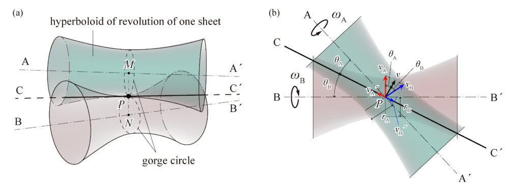
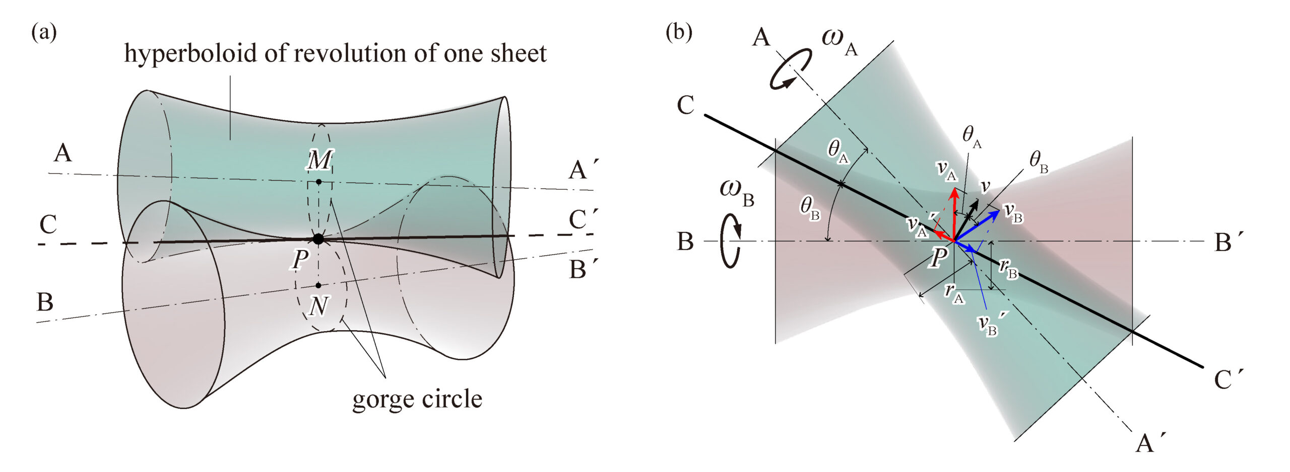
When the two axes transmitting rotation are in a skew position (neither parallel nor intersecting), the contact surface is a simple hyperbolic surface of revolution.
It is one of the ruled surfaces whose parent line is a straight line. It can be formed with one of the two axes in the twisted position as the axis of rotation (Fig. 1 (a)).
When two single hyperbolic surfaces of revolution are in contact, the part of each surface with the smallest diameter (the neck of the surface) is called the “gorge circle.” Let \(v_A\) and \(v_B\) be the velocities of each surface at the point of contact P on the gorge circle. Let the angular velocities be \(\omega_A\) and \(\omega_B\), and the radii of the throat circle be \(r_A\) and \(r_B\), then \(v_A = r_A\omega_A, v_B = r_B\omega_B\).
As shown in Fig. 1 (b), if we decompose this velocity into a velocity along the contact line \(CC^{\prime}\) and a velocity perpendicular to it, the velocities perpendicular to \(CC^{\prime}\) must be equal to make rolling contact. If the angles between \(CC^{\prime}\) and the axes of the respective cars are \(\theta_A\) and \(\theta_B\), then
$$ v_A\cos\theta_A=v_B\cos\theta_B,\quad r_A\omega_A\cos\theta_A=r_B\omega_B\cos\theta_B$$
Thus, the velocity ratio \(u\) is,
$$ u = \frac{\omega_A}{\omega_B}=\frac{r_A\cos\theta_A}{r_B\cos\theta_B} $$
If the number of revolutions at time \(t\) on the \(A\) axis is \(n_A\) and the number of revolutions at time \(t\) on the \(B\) axis is \(n_B\), the following relationship is obtained.
$$ v_A=\frac{\pi r_A n_A}{2t},\quad v_B=\frac{\pi r_B n_B}{2t} $$
Therefore,
$$ \frac{\pi r_A n_A}{2t}\cos\theta_A=\frac{\pi r_B n_B}{2t}\cos\theta_B $$
Thereby,
$$ \frac{n_A}{n_B}=\frac{r_A\cos\theta_A}{r_B\cos\theta_B}=u $$
bevel gear

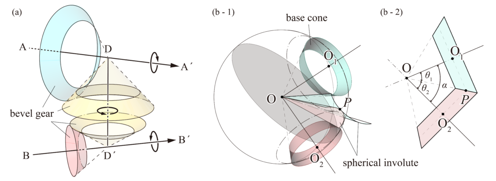
Putting this technology into practical use is often difficult because it is not easy to manufacture accurately and causes a lot of friction and wear. Therefore, a shaft \(DD^{\prime}\) intersecting the two axes can be created, and two conical wheels can be attached to it to transmit rotational motion between the two axes by making contact with the conical wheels on each axis (Fig. 2 (a)).
A bevel gear with a conical pitch surface and teeth is used to transmit rotation between two orthogonal axes. When considering the mutual motion of gears, a point on the gear moves on a sphere centered at the intersection of the two axes, so the tooth profile is treated as a spherical curve to investigate the properties of the tooth profile. In the case of involute gears, the tooth profile is spherical involute.
In the above figure (Fig. 2 (b-1)), there is a circle tangent to the cone with axes \(OO_1\) and \(OO_2\), and when the circle rolls on the side of the cone with axis \(OO_1\), the curved surface drawn by the radius \(OP\) is the tooth surface of the mating gear. The curve drawn by the contact point P is a spherical involute. The cone at this point is called the base cone. The intersection of the circle passing through \(O_1\) and \(O_2\) and the aforementioned circle tangent to the base cone is the mother line, and the cones with axes at \(OO_1\) and \(OO_2\) respectively are called pitch cones.
In the above figure (Fig. 2 (b-2)), when the angle between the two axes is \(\alpha\), the angle between the axis and the axis of rotation of each pitch cone is \(\theta_1\) and \(\theta_2\), and the number of teeth is \(z_1\) and \(z_2\), the following equation holds.
$$ \tan\theta_1=\frac{\sin\alpha}{(z_2/z_1)+\cos\alpha} $$
$$ \tan\theta_2=\frac{\sin\alpha}{(z_1/z_2)+\cos\alpha} $$
That is, \( \displaystyle\tan\theta_1=\frac{z_1}{z_2} \) and \(\displaystyle\tan\theta_2=\frac{z_2}{z_1}\) when \(\alpha=90^{\circ}\).
Also, when \(\alpha=90^{\circ}\) and \(z_1=z_2\), \(\theta_1=\theta_2=45^{\circ}\). The gear, in this case, is called mitre gear.
skew bevel gear
In consideration of problems caused by manufacturing, friction, and wear, when transmitting rotation by rolling contact between two axes in a twisted position, a gear with teeth beveled in the bushing direction as a pitch surface on a part of the single hyperbolic rotating surface is called a skew bevel gear.
The gear is often used when the two axes are orthogonal to each other in the form of a projected surface, and the gear is called a hypoid gear when two cones with different axes are in point contact, and the teeth are carved as pitch cones. Unlike bevel gears, hypoid gears have the advantage of extending the shaft in both directions. The smaller gear is threaded and has stronger teeth than bevel gears.


コメント